


NI5010-1 Network Card Settings and Configuration
MICOM-INTERLAN, INC.
NI5010-1
NIC Type | Ethernet |
Network Transfer Rate | 10Mbps |
Data Bus | 8-bit ISA |
Topology | Linear Bus |
Wiring Type | AUI transceiver via DB-15 port RG-58A/U 50ohm coaxial |
Boot ROM | Available |
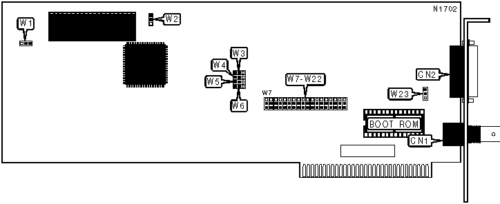
CONNECTIONS | |||
Function | Label | Function | Label |
RG-58A/U 50ohm coaxial port | CN1 | AUI transceiver via DB-15 port | CN2 |
USER CONFIGURABLE SETTINGS | |||
Function | Label | Position | |
| » | Receive Buffer size selected at 2KB | W1 | Pins 2 & 3 closed |
Receive Buffer size selected at 8KB | W1 | Pins 1 & 2 closed | |
| » | Transceiver type AC | W2 | Pins 2 & 3 closed |
Transceiver type DC | W2 | Pins 1 & 2 closed | |
| » | IRQ3 enabled | W7 | Pins 2 & 3 closed |
IRQ3 disabled | W7 | Pins 1 & 2 closed | |
DMA CHANNEL SELECTION | |||
DMA | W8 | W14 | |
| » | 3 | Pins 2 & 3 closed | Pins 1 & 2 closed |
| » | 1 | Pins 1 & 2 closed | Pins 2 & 3 closed |
Disabled | Pins 2 & 3 closed | Pins 2 & 3 closed | |
BASE I/O ADDRESS SELECTION | ||||||
Setting | W9 | W10 | W11 | W12 | W13 | |
200h | 2 & 3 | 2 & 3 | 2 & 3 | 2 & 3 | 1 & 2 | |
220h | 1 & 2 | 2 & 3 | 2 & 3 | 2 & 3 | 1 & 2 | |
240h | 2 & 3 | 1 & 2 | 2 & 3 | 2 & 3 | 1 & 2 | |
260h | 1 & 2 | 1 & 2 | 2 & 3 | 2 & 3 | 1 & 2 | |
280h | 2 & 3 | 2 & 3 | 1 & 2 | 2 & 3 | 1 & 2 | |
2A0h | 1 & 2 | 2 & 3 | 1 & 2 | 2 & 3 | 1 & 2 | |
2C0h | 2 & 3 | 1 & 2 | 1 & 2 | 2 & 3 | 1 & 2 | |
2E0h | 1 & 2 | 1 & 2 | 1 & 2 | 2 & 3 | 1 & 2 | |
| » | 300h | 2 & 3 | 2 & 3 | 2 & 3 | 1 & 2 | 1 & 2 |
320h | 1 & 2 | 2 & 3 | 2 & 3 | 1 & 2 | 1 & 2 | |
340h | 2 & 3 | 1 & 2 | 2 & 3 | 1 & 2 | 1 & 2 | |
360h | 1 & 2 | 1 & 2 | 2 & 3 | 1 & 2 | 1 & 2 | |
380h | 2 & 3 | 2 & 3 | 1 & 2 | 1 & 2 | 1 & 2 | |
3A0h | 1 & 2 | 2 & 3 | 1 & 2 | 1 & 2 | 1 & 2 | |
3C0h | 2 & 3 | 1 & 2 | 1 & 2 | 1 & 2 | 1 & 2 | |
3E0h | 1 & 2 | 1 & 2 | 1 & 2 | 1 & 2 | 1 & 2 | |
Note: The pins designated above should be in the closed position. | ||||||
CABLE TYPE SELECTION | ||||||
Type | W3 | W4 | W5 | W6 | W23 | |
| » | RG-58A/U 50ohm coaxial | 2 & 3 | 2 & 3 | 2 & 3 | 2 & 3 | 2 & 3 |
AUI transceiver via DB-15 port | 1 & 2 | 1 & 2 | 1 & 2 | 1 & 2 | 1 & 2 | |
Note: The pins designated should be in the closed position. | ||||||
BOOT ROM STARTING ADDRESS SELECTION | |||||||||
Address | W15 | W16 | W17 | W18 | W19 | W20 | W21 | W22 | |
| » | Disabled | 2 & 3 | 2 & 3 | 2 & 3 | 2 & 3 | 2 & 3 | 2 & 3 | 2 & 3 | 2 & 3 |
C8000h | 2 & 3 | 2 & 3 | 2 & 3 | 1 & 2 | 2 & 3 | 2 & 3 | 1 & 2 | 1 & 2 | |
C9000h | 1 & 2 | 2 & 3 | 2 & 3 | 1 & 2 | 2 & 3 | 2 & 3 | 1 & 2 | 1 & 2 | |
CA000h | 2 & 3 | 1 & 2 | 2 & 3 | 1 & 2 | 2 & 3 | 2 & 3 | 1 & 2 | 1 & 2 | |
CB000h | 1 & 2 | 1 & 2 | 2 & 3 | 1 & 2 | 2 & 3 | 2 & 3 | 1 & 2 | 1 & 2 | |
CC000h | 2 & 3 | 2 & 3 | 1 & 2 | 1 & 2 | 2 & 3 | 2 & 3 | 1 & 2 | 1 & 2 | |
EB000h | 1 & 2 | 1 & 2 | 2 & 3 | 1 & 2 | 2 & 3 | 1 & 2 | 1 & 2 | 1 & 2 | |
EC000h | 2 & 3 | 2 & 3 | 1 & 2 | 1 & 2 | 2 & 3 | 1 & 2 | 1 & 2 | 1 & 2 | |
ED000h | 1 & 2 | 2 & 3 | 1 & 2 | 1 & 2 | 2 & 3 | 1 & 2 | 1 & 2 | 1 & 2 | |
EE000h | 2 & 3 | 1 & 2 | 1 & 2 | 1 & 2 | 2 & 3 | 1 & 2 | 1 & 2 | 1 & 2 | |
EF000h | 1 & 2 | 1 & 2 | 1 & 2 | 1 & 2 | 2 & 3 | 1 & 2 | 1 & 2 | 1 & 2 | |
Note:The pins designated should be in the closed position. Note:A total of 40 base address settings are available. The switches are a binary representation of the decimal memory addresses. W22 is the Most Significant Bit and switch W15 is the Least Significant Bit. The switches have the following decimal values: W22=524288, W21=262144, W20=131072, W19=65536, W18=32768, W17=16384, W16=8192, and W15=4096. Turn off the switches and add the values of the switches to obtain the correct memory address. (Off=1, On=0) | |||||||||


My Books

