


V12LC-2 Motherboard Settings and Configuration
ACER, INC.
V12LC-2
Device Type | Mainboard |
Processor | CX 6X86/AM K5/Pentium |
Processor Speed | 75/90/100/120/133/150MHz |
Chip Set | Unidentified |
Video Chip Set | Cirrus Logic |
Maximum Onboard Memory | 128MB |
Maximum Video Memory | 2MB |
Cache | 256KB |
BIOS | Unidentified |
Dimensions | 330mm x 218mm |
I/O Options (backplane) | bus mouse port, Ethernet 10BaseT connector, floppy drive interface, green PC connector, IDE interfaces (2), parallel port, PS/2 mouse interface, PS/2 keyboard interface, serial ports (2), VGA feature connector, VGA port, riser slot |
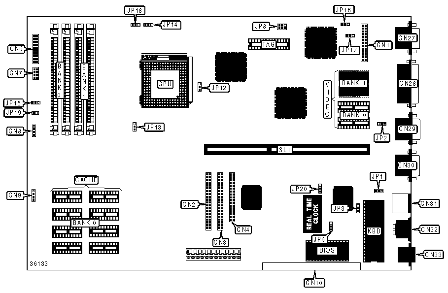
CONNECTIONS | |||
Purpose | Location | Purpose | Location |
VGA feature connector | CN1 | IDE interface LED | CN8 |
IDE interface 1 | CN2 | Network/multimedia interface | CN10 |
IDE interface 2 | CN3 | VGA port | CN27 |
Floppy drive interface | CN4 | Parallel port | CN28 |
Power LED & keylock | CN6/pins 1 - 5 | Serial port 2 | CN29 |
Speaker | CN6/pins 7 - 10 | Serial port 1 | CN30 |
Turbo LED | CN6/pins 12 & 13 | PS/2 mouse interface | CN31 |
Turbo switch | CN6/pins 15 - 17 | PS/2 keyboard interface | CN32 |
Reset switch | CN6/pins 19 & 20 | RJ-45 phone jack | CN33 |
Power LED & keylock | CN7/pins 1 - 4 | Riser slot | SL1 |
Reset switch | CN7/pins 6 & 7 |
|
|
USER CONFIGURABLE SETTINGS | |||
Function | Label | Position | |
» | Factory configured - do not alter | CN9 | Reserved |
» | BIOS type select Acer | JP1 | Pins 1 & 2 closed |
| BIOS type select OEM | JP1 | Pins 2 & 3 closed |
» | Password disabled | JP2 | Pins 2 & 3 closed |
| Password enabled | JP2 | Pins 1 & 2 closed |
» | BIOS ROM type select flash ROM | JP3 | Pins 2 & 3 closed |
| BIOS ROM type select EPROM | JP3 | Pins 1 & 2 closed |
» | Onboard SMC665/669 enabled | JP6 | Pins 2 & 3 closed |
| Onboard SMC665/669 disabled | JP6 | Pins 1 & 2 closed |
» | CPU type select P54C or AMD K5 | JP12 | Pins 1 & 2 closed |
| CPU type select Cyrix M1 | JP12 | Pins 2 & 3 closed |
» | Reset function | JP15 | Pins 2 & 3 closed |
| Suspend mode function | JP15 | Pins 1 & 2 closed |
» | Factory configured - do not alter | JP19 | Open |
» | Flash ROM control select normal work | JP20 | Pins 2 & 3 closed |
| Flash ROM control select boot block | JP20 | Pins 1 & 2 closed |
SIMM CONFIGURATION | ||
Size | Bank 0 | Bank 1 |
8MB | (2) 1M x 36 | None |
16MB | (2) 2M x 36 | None |
16MB | (2) 1M x 36 | (2) 1M x 36 |
24MB | (2) 2M x 36 | (2) 1M x 36 |
32MB | (2) 4M x 36 | None |
32MB | (2) 2M x 36 | (2) 2M x 36 |
40MB | (2) 4M x 36 | (2) 1M x 36 |
48MB | (2) 4M x 36 | (2) 2M x 36 |
64MB | (2) 8M x 36 | None |
64MB | (2) 4M x 36 | (2) 4M x 36 |
72MB | (2) 8M x 36 | (2) 1M x 36 |
80MB | (2) 8M x 36 | (2) 2M x 36 |
96MB | (2) 8M x 36 | (2) 4M x 36 |
128MB | (2) 8M x 36 | (2) 8M x 36 |
CACHE CONFIGURATION |
Note: Cache configuration is unidentified. |
VIDEO MEMORY CONFIGURATION | ||
Size | Bank 0 | Bank 1 |
1MB | (2) 256K x 16 | None |
2MB | (2) 256K x 16 | (2) 256K x 16 |
CPU SPEED SELECTION | |
Speed | JP8 |
75MHz | Pins 1 & 4 closed |
90MHz | Pins 2 & 5 closed |
100MHz | Pins 3 & 6 closed |
120MHz | Pins 2 & 5 closed |
133MHz | Pins 3 & 6 closed |
150MHz | Pins 2 & 5 closed |
CPU MULTIPLIER SELECTION (INTEL) | ||
Multiplier | JP14 | JP18 |
» 1.5x | Pins 1 & 2 closed | Pins 1 & 2 closed |
2x | Pins 2 & 3 closed | Pins 1 & 2 closed |
2.5x | Pins 2 & 3 closed | Pins 2 & 3 closed |
3x | Pins 1 & 2 closed | Pins 2 & 3 closed |
CPU MULTIPLIER SELECTION (CX 6X86 & AM K5) | ||
Multiplier | JP14 | JP18 |
» 1x, 1.5x, 3x | Pins 1 & 2 closed | Pins 1 & 2 closed |
1x | Pins 2 & 3 closed | Pins 1 & 2 closed |
1x, 1.5x, 3x | Pins 1 & 2 closed | Pins 2 & 3 closed |
1x | Pins 2 & 3 closed | Pins 2 & 3 closed |
CPU VOLTAGE SELECTION | |
Voltage | JP13 |
» 3.3825v | Pins 1 & 2 closed |
3.5250v | Pins 2 & 3 closed |
CN1 CONNECTOR SELECTION | ||
Setting | JP16 | JP17 |
» Feature connector | Pins 1 & 2 closed | Pins 1 & 2 closed |
I2C connector | Pins 2 & 3 closed | Pins 2 & 3 closed |


My Books

