UN-1075 Hard Disk/Floppy Controller Settings and Configuration
DTK COMPUTER INC.
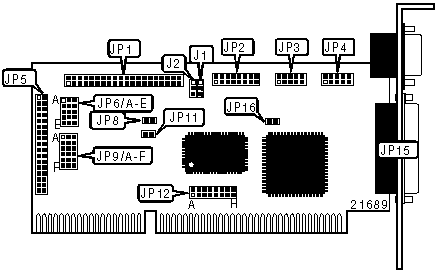
UN-1075
Card Type | Hard drive controller card |
Hard Drives supported | Two IDE (AT or XT) drives |
Floppy drives supported | Two 360KB, 720KB, 1.2MB, or 1.44MB drives |
Data Bus | 16-bit ISA |
Card Size | Three-quarter length, half-height card |
CONNECTIONS | |||
Function | Location | Function | Location |
40-pin primary IDE(AT) connector | JP1 | 34-pin cable connector - floppy drive | JP5 |
16-pin game port connector | JP2 | Hard disk drive LED connector | JP8 |
10-pin serial port 1 connector | JP3 | 25-pin parallel port connector- external | JP15 |
10-pin serial port 2 connector | JP4 | ||
USER CONFIGURABLE SETTINGS | |||
Function | Label | Position | |
| » | Floppy drive order is normal (A:, B:) | JP6/A | Pins 1 & 2 closed |
| Floppy drive order is reversed (B:, A:) | JP6/A | Pins 2 & 3 closed | |
| » | Floppy drive address is 370h-377h | JP6/B | Pins 1 & 2 closed |
| Floppy drive address is 3F0h-3F7h | JP6/B | Pins 2 & 3 closed | |
| » | IDE(AT) interface enabled | JP6/C | Pins 1 & 2 closed |
| IDE(AT) interface disabled | JP6/C | Pins 2 & 3 closed | |
| » | IDE primary address is 367h, 377h, 170h-177h | JP6/D | Pins 1 & 2 closed |
| IDE secondary address is 3F6h, 3F7h, 1F0h-1F7h | JP6/D | Pins 2 & 3 closed | |
| » | Floppy drive interface enabled | JP6/E | Pins 1 & 2 closed |
| Floppy drive interface disabled | JP6/E | Pins 2 & 3 closed | |
| » | Game port enabled | JP16 | Closed |
| Game port disabled | JP16 | Open | |
PARALLEL PORT ADDRESS SELECTION | |||
Setting | JP9/E | JP9/F | |
| » | LPT1 (378h) | Pins 2 & 3 closed | Pins 1 & 2 closed |
LPT2 (278h) | Pins 1 & 2 closed | Pins 2 & 3 closed | |
LPT3 (3BCh) | Pins 1 & 2 closed | Pins 1 & 2 closed | |
Disabled | Pins 2 & 3 closed | Pins 2 & 3 closed | |
SERIAL PORT 1 ADDRESS SELECTION | |||
Setting | JP9/A | JP9/B | |
| » | COM1 (3F8h) | Pins 1 & 2 closed | Pins 2 & 3 closed |
COM3 (3E8h) | Pins 2 & 3 closed | Pins 1 & 2 closed | |
COM4 (2E8h) | Pins 1 & 2 closed | Pins 1 & 2 closed | |
Disabled | Pins 2 & 3 closed | Pins 2 & 3 closed | |
SERIAL PORT 2 ADDRESS SELECTION | |||
Setting | JP9/C | JP9/D | |
| » | COM2 (2F8h) | Pins 1 & 2 closed | Pins 2 & 3 closed |
COM3 (3E8h) | Pins 1 & 2 closed | Pins 1 & 2 closed | |
COM4 (2E8h) | Pins 2 & 3 closed | Pins 1 & 2 closed | |
Disabled | Pins 2 & 3 closed | Pins 2 & 3 closed | |
SERIAL PORT 1 INTERRUPT SELECTION | ||||
IRQ | JP12/A | JP12/B | JP12/C | |
IRQ3 | Open | Closed | Open | |
| » | IRQ4 | Closed | Open | Open |
IRQ5 | Open | Open | Closed | |
SERIAL PORT 2 INTERRUPT SELECTION | ||||
IRQ | JP12/D | JP12/E | JP12/F | |
| » | IRQ3 | Closed | Open | Open |
IRQ4 | Open | Closed | Open | |
IRQ5 | Open | Open | Closed | |
PARALLEL PORT INTERRUPT SELECTION | |||
IRQ | JP12/G | JP12/H | |
| » | 7 | Closed | Open |
5 | Open | Closed | |
PARALLEL PORT MODE SELECTION | ||
Mode | Label | Position |
Uni-directional | JP11 | Closed |
Bi-directional | JP11 | Open |
IDEIOR PATH SELECTION | |||
Function | Label | Position | |
W83758p – IOROP (buffer) | J1 | Pins 1 & 2 closed | |
| » | ATBUS IOR | J1 | Pins 2 & 3 closed |
IDEIOW PATH SELECTION | |||
Function | Label | Position | |
W83758p – IOWOP (buffer) | J2 | Pins 1 & 2 closed | |
| » | ATBUS IOW | J2 | Pins 2 & 3 closed |
My Books

