PM3755U2B Hard Disk/Floppy Controller Settings and Configuration
DISTRIBUTED PROCESSING TECHNOLOGY
PM3755U2B
Card Type | Hard drive controller |
Chip Set | Unidentified |
Maximum Onboard Memory | 256MB DRAM |
I/O Options | SCSI connectors (2), expansion module connectors (2) |
Hard Drives supported | Up to 15 Ultra2/LVD Wide SCSI devices Up to 45 Wide SCSI-2 or Ultra-wide SCSI devices with expansion board upgrades |
Floppy drives supported | None |
Data Bus | 64-bit PCI |
Card Size | Full-length |
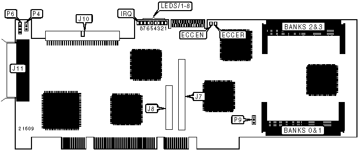
CONNECTIONS | |||
Function | Label | Function | Label |
32-bit header connector to expansion module | J7 | 68-pin SCSI connector Ch. 0 - external | J11 |
64-bit header connector to expansion module | J8 | 4-pin connector - drive active LED | P6 |
68-pin SCSI connector Ch. 0 - internal | J10 | ||
Note: Header connector to BB4050 battery module is unidentified | |||
USER CONFIGURABLE SETTINGS | ||
Function | Label | Position |
NVRAM reset to default settings | P4 | Pins 1 & 2 closed |
NVRAM setup parameters retained | P4 | Pins 3 & 4 closed |
Load enabled | P9 | Pins 1 & 2 closed |
Run enabled | P9 | Pins 3 & 4 closed |
DIMM MEMORY CONFIGURATION | ||||
Size | Bank 0 | Bank 1 | Bank 2 | Bank 3 |
16MB | (1)2MB x 64 | None | None | None |
32MB | (1)2MB x 64 | (1)2MB x 64 | None | None |
48MB | (1)2MB x 64 | (1)2MB x 64 | (1)2MB x 64 | None |
64MB | (1)2MB x 64 | (1)2MB x 64 | (1)2MB x 64 | (1)2MB x 64 |
64MB | (1)8MB x 64 | None | None | None |
80MB | (1)8MB x 64 | (1)2MB x 64 | None | None |
144MB | (1)8MB x 64 | (1)8MB x 64 | (1)2MB x 64 | None |
160MB | (1)8MB x 64 | (1)8MB x 64 | (1)2MB x 64 | None |
128MB | (1)8MB x 64 | (1)8MB x 64 | None | None |
192MB | (1)8MB x 64 | (1)8MB x 64 | (1)8MB x 64 | None |
208MB | (1)8MB x 64 | (1)8MB x 64 | (1)8MB x 64 | (1)2MB x 64 |
256MB | (1)8MB x 64 | (1)8MB x 64 | (1)8MB x 64 | (1)8MB x 64 |
DIAGNOSTIC LED(S) | |||
LED | Color | Status | Condition |
LED1 | Unidentified | On | Controller is ready; interrupts are enabled |
LED1 | Unidentified | Off | Controller is inactive |
LED1 | Unidentified | Blinking | Controller is active |
LED2 | Unidentified | On | Non-maskable interrupt (NMI) detected |
LED2 | Unidentified | Off | NMI not detected |
LED3 | Unidentified | On | Controller in idle loop mode |
LED3 | Unidentified | Off | Controller not in idle loop mode |
LED4 | Unidentified | On | Interrupt is being processed |
LED4 | Unidentified | Off | Interrupt is not being processed |
LED5 | Unidentified | Off | Not used |
LED6 | Unidentified | On | Cache controller is using DMA to perform a data transfer |
LED6 | Unidentified | Off | Cache controller is not using DMA to perform a data transfer |
LED7 | Unidentified | On | Parity is being generated |
LED7 | Unidentified | Off | Parity is not being generated |
LED8 | Unidentified | On | Command detected on SCSI |
LED8 | Unidentified | Off | Command not detected on SCSI |
IRQ | Unidentified | On | Interrupt has been activated on host PCI bus |
IRQ | Unidentified | Off | Interrupt has not been activated on host PCI bus |
ECCEN | Green | On | Cache is ECC protected |
ECCEN | Green | Off | Cache is not ECC protected |
ECCER | Red | On | Error detected. Cache failure information reported |
ECCER | Red | Off | Error not detected |
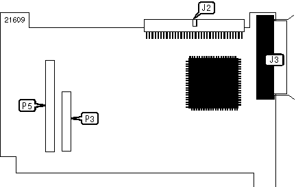
SX4055U2-1 EXPANSION MODULE
CONNECTIONS | |||
Function | Label | Function | Label |
68-pin SCSI connector Ch. 1- internal | J2 | 64-bit auxiliary header connector to Controller card | P3 |
68-pin SCSI connector Ch. 1 - external | J3 | Header connector to Controller card | P5 |
Note: SX4055U2-1 expansion module supports an additional 15 Ultra2/LVD Wide SCSI devices | |||
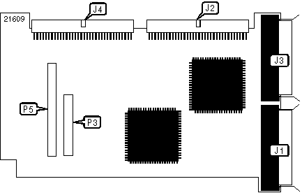
SX4055U2-2
CONNECTIONS | |||
Function | Label | Function | Label |
68-pin SCSI connector Ch. 2 - external | J1 | 68-pin SCSI connector Ch. 2 - internal | J4 |
68-pin SCSI connector Ch. 1- internal | J2 | 64-bit auxiliary header connector to Controller card | P3 |
68-pin SCSI connector Ch. 1 - external | J3 | Header connector to Controller card | P5 |
Note: SX405U2-2 expansion module supports an additional 30 Ultra2/LVD Wide SCSI devices | |||
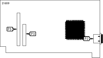
SX4055F FC-AL
CONNECTIONS | |||
Function | Label | Function | Label |
HSSDC FC-AL connector Ch. 1 - external | P2 | Header connector to Controller card | P5 |
64-bit auxiliary header connector to Controller card | P3 | ||
Note: Fibre channel provided by expansion module supports up to 126 additional devices | |||
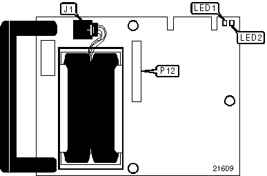
BB4050 BATTERY BACKUP MODULE
CONNECTIONS | |||
Function | Label | Function | Label |
Battery cable connector | J1 | Header connector to Controller card | P12 |
Note: BB4050 battery backup module may only be installed on a PM3755U2B Controller | |||
DIAGNOSTIC LED(S) | |||
LED | Color | Status | Condition |
LED1 | Unidentified | On | Trickle charge activity detected |
LED1 | Unidentified | Off | Trickle charge activity not detected |
LED2 | Unidentified | On | Charging/recharging mode initiated |
LED2 | Unidentified | Off | Battery module not charging |
My Books

