DX144M modem/telephone/ISDN Settings and Configuration
PENRIL DATABILITY NETWORKS
DX144M
Modem Type | Data (synchronous/asynchronous)/Fax |
Maximum Data Rate | 14.4Kbps |
Maximum Fax Rate | 14.4Kbps |
Data Bus | External |
Fax Class | Class I & II |
Data Modulation Protocol | Bell 103A/212A, 208A/B ITU-T V.21, V.22, V.22bis, V.23, V.32, V.32bis |
Fax Modulation Protocol | ITU-T V.17, V.27ter, V.29 |
Error Correction/Compression | MNP5, V.42, V.42bis |
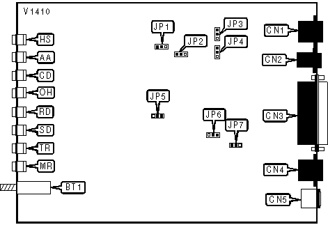
CONNECTIONS | |||
Purpose | Location | Purpose | Location |
Lease line out | CN1 | Diagnostic connector | CN4 |
Line in | CN2 | AC power | CN5 |
RS-232/422 | CN3 | Data/Voice | BT1 |
A/A1 - MI/MIC CONTROL | ||
Control Type | JP3 | JP4 |
| » A/A1 control. | Pin 1 & 2 closed. | Pin 1 & 2 closed. |
MI/MIC control. | Pin 2 & 3 closed. | Pin 2 & 3 closed. |
DIAL/LEASE LINE | ||
Line Type | JP1 | JP2 |
| » Dial line connected. | Pin 1 & 2 closed. | Pin 1 & 2 closed. |
Lease line connected. | Pin 2 & 3 closed. | Pin 2 & 3 closed. |
DTE CONNECTION - PIN 25 | |
Function | JP6 |
Analog loopback (input). | Pin 1 & 2 closed. |
| » Test mode indicator (output). | Pin 2 & 3 closed. |
FACTORY CONFIGURED SETTINGS - DO NOT ALTER | |
Jumper | Setting |
JP5 | Pin 2 & 3 closed. |
FRAME/SIGNAL GROUND | |
Ground Type | JP7 |
Frame and signal ground connected. | Pin 1 & 2 closed. |
| » Frame and signal ground not connected. | Pin 2 & 3 closed. |
DIAGNOSTIC LED(S) | |||
LED | Color | Status | Condition |
HS | Red | On | Modem is operating at 7200bps or faster |
HS | Red | Off | Modem is operating at slower than 7200bps |
AA | Red | On | Auto-answer enabled |
AA | Red | Off | Auto-answer disabled |
AA | Red | Blinking | Phone is ringing |
CD | Red | On | Carrier signal detected |
CD | Red | Off | Carrier signal not detected |
OH | Red | On | Modem is off-hook |
OH | Red | Off | Modem is on-hook |
RD | Red | On | Modem is receiving data |
RD | Red | Off | Modem is not receiving data |
SD | Red | On | Modem is transmitting data |
SD | Red | Off | Modem is not transmitting data |
TR | Red | On | DTR signal is high |
TR | Red | Flashing | Voice mode |
MR | Red | On | Modem ready |
MR | Red | Off | Test mode enabled |
Proprietary AT Command Set
ADMINISTRATIVE PASSWORD | |
Type: | Configuration |
Format: | AT [cmds] /A |
Example: | AT &Z=/ASECURITY <CR> |
Description: | Set administrative password; password-protects use of certain Hayes commands. |
Note | SECURITY is the modem’s default password. |
AUTO-RETRAIN | |
Type: | Configuration |
Format: | AT [cmds] %En [cmds] |
Example: | AT %E1 <CR> |
Description: | Selects auto-retrain mode. |
Command | Function |
%E0 | Auto-retrain disabled. |
| » %E1 | Auto-retrain enabled. |
BUFFER MODE/SPEED CONVERSION | |
Type: | Configuration |
Format: | AT [cmds] \Bn [cmds] |
Example: | AT \B1 &W <CR> |
Description: | Controls buffer mode/speed conversion |
Command | Function |
\B0 | Speed conversion disabled. |
| » \B1 | Speed conversion enabled. |
CONNECTION SPEED LOWER LIMIT | |
Format | AT [cmds] S44=n [cmds] |
Example: | AT S44=14 <CR> |
Default: | 14 |
Range: | 4 - 14 |
Unit: | Bit-mapped |
Description: | Selects minimum data rate. |
Command | Function |
4 | Select 19.2Kbps speed. |
5 | Not used. |
6 | Select 14.4Kbps speed. |
7 | Select 12Kbps speed. |
8 | Select 9600bps speed. |
9 | Select 7200bps speed. |
10 | Select 4800bps speed. |
11 | Select 2400bps speed. |
12 | Select 1200bps speed. |
| » 14 | Select 0 - 300bps speed. |
CONNECTION SPEED UPPER LIMIT | |
Format | AT [cmds] S43=n [cmds] |
Example: | AT S43=8 <CR> |
Default: | 6 |
Range: | 4 - 16 |
Unit: | Bit-mapped |
Description: | Selects maximum data rate. |
Note: DX V.32terbo M default setting is 4 for this S-register. | |
Command | Function |
4 | Select 19.2Kbps speed. |
5 | Select 16.8Kbps speed. |
6 | Select 14.4Kbps speed. |
7 | Select 12Kbps speed. |
| » 8 | Select 9600bps speed. |
9 | Select 7200bps speed. |
10 | Select 4800bps speed. |
11 | Select 2400bps speed. |
12 | Select 1200bps speed. |
14 | Select 0 - 300bps speed. |
15 | Select 1200/75bps speed. |
16 | Select EIA control. |
DIAL | |
Type: | Immediate |
Format: | AT [cmds] D<#> [; cmds] |
Example: | AT H1 DT 9W *70, 1(303) 555-1212 <CR> |
Description: | Dials telephone number according to any modifiers included in the string. |
Modifier | Function |
DL | Links a stored phone number to another number as an alternate. |
DP | Pulse dialing enabled. |
DS=c | Number in memory location c dialed. |
DT | Tone dialing enabled. |
DW | Dialing resumed following dial tone detection. |
D: | Dialing resumed following dial tone detection. |
D/R | Modem is configured for Dial Line Auto-Recovery. |
D, | Dialing paused for amount of time specified in S8 register. |
D< | Dialing paused for amount of time specified in S8 register. |
D; | Modem returned to command mode after dialing. |
D& | Flash function initiated. Modem commanded to go on-hook for specified time. |
D! | Flash function initiated. Modem commanded to go on-hook for specified time. |
D@ | Modem waits for a ring-back signal followed by silence up to the time specified in S7 prior to executing the rest of the dial string. |
DIALING MESSAGE | |
Type: | Configuration |
Format: | AT [cmds] \Dn [cmds] |
Example: | AT \D0 &W <CR> |
Description: | Controls dialing message. |
Command | Function |
| » \D0 | "Dialing" message disabled. |
\D1 | "Dialing" message enabled. |
DTE SPEED | |
Type: | Register |
Format: | AT [cmds] S61n [cmds] |
Example: | AT S61=2 <CR> |
Description: | Selects the current DTE speed. |
Command | Function |
0 | Select 115.2Kbps speed. |
1 | Select 57.6Kbps speed. |
| » 2 | Select 38.4Kbps speed. |
3 | Select 19.2Kbps speed. |
4 | Select 9600bps speed. |
5 | Select 7200bps speed. |
6 | Select 4800bps speed. |
7 | Select 2400bps speed. |
8 | Select 1800bps speed. |
9 | Select 1200bps speed. |
10 | Select 600bps speed. |
11 | Select 300bps speed. |
INACTIVITY TIMER | |
Type: | Immediate |
Format: | AT [cmds] \T=n [cmds] |
Example: | AT \T=0 <CR> |
Default: | 0 |
Range: | 0 - 90 |
Unit: | 1 minutes |
Description: | Sets the length of time that the modem does not receive information before it disconnects. |
MANUAL RESPONSE PASSWORD | |
Type: | Configuration |
Format: | AT [cmds] /P |
Example: | AT &Z22=/PBLUE <CR> or AT &Z42=5551212/PGREEN<CR> |
Description: | Sets password for Manual response password; with or without callback. |
MAXIMUM BLOCK SIZE FOR TRANSMISSION | |
Type: | Configuration |
Format: | AT [cmds] \An [cmds] |
Example: | AT \A3 \B0 <CR> |
Description: | Sets the maximum transmittable block size. |
Command | Function |
\A0 | Maximum MNP block size is 64 characters. |
\A1 | Maximum MNP block size is 128 characters. |
\A2 | Maximum MNP block size is 192 characters. |
| » \A3 | Maximum MNP block size is 256 characters. |
MNP CLASS - LIMIT | |
Type: | Configuration |
Format: | AT [cmds] \Cn [cmds] |
Example: | AT \C5 &W <CR> |
Description: | Selects MNP class. |
Note: | This option is not in effect until modem goes off-line. |
Command | Function |
\C1 | MNP class 1. |
\C2 | MNP class 1 & 2. |
\C3 | MNP class 1 - 3. |
\C4 | MNP class 1 - 4. |
| » \C5 | MNP class 1- 5. |
PRODUCT CODE | |
Type: | Configuration |
Format: | AT [cmds] In [cmds] |
Example: | AT I0 &W <CR> |
Description: | Selects product code or checksum. |
Command | Function |
I0 | Request product code. |
I1 | Request checksum for the ALX modem’s software. |
I2 | Request verification of software checksum. |
I3 | Request the following for each EPROM chip, part and revision number |
RECEIVE/TRANSMIT SPACE DISCONNECT | |
Type: | Configuration |
Format: | AT [cmds] Yn [cmds] |
Example: | AT Y1 &W <CR> |
Description: | Controls receive/transmit space disconnect. |
Command | Function |
Y0 | Receive space connect and transmit space disconnect disabled. |
| » Y1 | Receive space connect and transmit space disconnect enabled. |
Y2 | Transmit space disconnect enabled; receive space disconnect disabled. |
Y3 | Receive space disconnect enabled; transmit space disconnect disabled. |
TRANSMIT LEVEL - DIAL | |
Type: | Configuration |
Format: | AT [cmds] -Ln [cmds] |
Example: | AT -L1 &W <CR> |
Description: | Controls transmit level. |
Command | Function |
-L0 | Permissive transmit level enabled. |
| » -L1 | Programmable transmit level enabled. |
USER-DEFINED TEXT STRING | |
Type: | Configuration |
Format: | AT [cmds] /U |
Example: | AT &Z0=/UGORDO <CR> |
Description: | Sends a response to remote terminal user after valid password is received. |
V.25bis MODE | |
Type: | Configuration |
Format: | AT [cmds] %Vn [cmds] |
Example: | AT %V2 &W <CR> |
Description: | Selects V.25bis mode. |
Command | Function |
%V0 | Hayes mode disabled, V.25bis mode asynchronous enabled. |
%V1 | V.25bis mode, sync bit oriented (HDLC) enabled. |
%V2 | V.25bis mode, synchronous character oriented enabled. |
V.32 MODE | |
Type: | Configuration |
Format: | AT [cmds] -Cn [cmds] |
Example: | AT -C1 &W <CR> |
Description: | Selects either V.32 extended or V.32bis mode. |
Command | Function |
-C0 | V.32 extended mode enabled. |
| » -C1 | V.32bis mode enabled. |
V.42 BREAK HANDLING | |
Type: | Configuration |
Format: | AT [cmds] \Kn [cmds] |
Example: | AT \K3 &W <CR> |
Description: | Selects the type of break in V.42. |
Command | Function |
\K0 | Normal break handling enabled. |
\K1 | Destructive/expedited break handling enabled. |
\K2 | Non-destructive/expedited break handling enabled. |
| » \K3 | Non-Destructive/non-expedited break handling enabled. |
V.42 DETECTION | |
Type: | Configuration |
Format: | AT [cmds] \En [cmds] |
Example: | AT \E1 &W <CR> |
Description: | Controls V.42 detection. |
Command | Function |
\E0 | V.42 detection disabled. |
| » \E1 | V.42 detection enabled. |
V.42 FLOW CONTROL | |
Type: | Configuration |
Format: | AT [cmds] \Qn [cmds] |
Example: | AT \Q3 &W <CR> |
Description: | Sets V.42 flow control. |
Command | Function |
\Q0 | Flow control disabled. |
\Q1 | RTS/CTS flow control enabled. |
\Q2 | DC1/DC2 flow control enabled. |
| » \Q3 | DC1/DC3 flow control enabled. |
V.42 MODE | |
Type: | Configuration |
Format: | AT [cmds] \Nn [cmds] |
Example: | AT \N3 &W <CR> |
Description: | Controls V.42 mode. |
Command | Function |
\N0 | Error correction disabled. |
\N1 | Mandatory mode for error correction enabled. |
\N2 | V.42 error correction enabled. |
| » \N3 | Automatic mode for error correction enabled. |
V.42 PASS-THROUGH FLOW CONRTOL | |||
Type: | Configuration | ||
Format: | AT [cmds] \Xn [cmds] | ||
Example: | AT \X7 &W <CR> | ||
Description: | Controls both DTE and DCE pass-through flow control. | ||
Command | DTE pass-through | DCE pass-through | |
| » \X0 | DTE and DCE pass-through flow disabled. | DTE and DCE pass-through flow disabled. | |
\X1 | DTE and DCE pass-through flow enabled. | DTE and DCE pass-through flow Enabled. | |
\X1, 0 | DTE pass-through flow enabled. | DCE pass-through flow disabled. | |
\X0, 1 | DTE pass-through flow disabled. | DCE pass-through flow enabled. | |
V.42 PROTOCOL | |
Type: | Configuration |
Format: | AT [cmds] \Pn [cmds] |
Example: | AT \P2 &W <CR> |
Description: | Selects V.42 protocol. |
Command | Function |
\P0 | LAPM protocol enabled. |
\P1 | MNP protocol enabled. |
| » \P2 | LAPM/MNP protocol enabled. |
V.42 RESULT CODES | |
Type: | Configuration |
Format: | AT [cmds] \Vn [cmds] |
Example: | AT \V1 %C1 <CR> |
Description: | Selects V.42 result codes. |
Command | Function |
\V0 | Regular V.42 result codes disabled. |
| » \V1 | Extended V.42 result codes enabled. |
V.42bis OPERATION | |
Type: | Configuration |
Format: | AT [cmds] \Mn [cmds] |
Example: | AT \M0 &W <CR> |
Description: | Controls V.42bis operation. |
Command | Function |
| » \M0 | V.42bis enabled. |
\M1 | V.42bis disabled. |
V.42bis STRING LENGTH | |
Type: | Immediate |
Format: | AT [cmds] \H=n [cmds] |
Example: | AT \H=13 <CR> |
Default: | 16 |
Range: | 6 - 250 |
Unit: | ASCII |
Description: | Sets the string length in V.42bis. |
VIEW V.42-RELATED CONFIGURATION | |
Type: | Configuration |
Format: | AT [cmds] \Sn [cmds] |
Example: | AT \S &W <CR> |
Description: | Shows the status of V.42 configuration. |
Proprietary V.25bis Command Set
CALL FAILURE INDICATOR | |||
Type: | Response | ||
Format: | CFIxx | ||
Description: | Indicates that the attempt to connect failed. | ||
Response | Name | Description: | |
CFIAB | Abort | The call was aborted because either no dialtone was detected or a character was received from the host computer. | |
CFICB | DCE Busy | An incoming call was detected after the dialing command was issued. | |
CFIET | Engaged Tone | A busy signal was detected. | |
CFIND | No Dial | Modem didn’t detect a dailtone. | |
CFINS | Not Stored | The memory address given did not contain a valid telephone number. | |
CFINT | No Tone | The remote party did not issue a response tone. | |
CFIRT | Ring Tone | A responding tone was detected, but the call timed out before it was completed. | |
COMMAND SET - AT | |
Type: | Immediate |
Format: | RHA |
Example: | RHA <CR> |
Description: | Switch to AT command set. |
CONNECTION | |
Type: | Response |
Format: | CNX |
Description: | A connection has been successfully established. |
INVALID | |
Type: | Response |
Format: | INVxx |
Example: | INVCU |
Description: | The modem was issued an improper command. The two letters following indicate the error. |
Code | Meaning |
INVCU | An error occurred in transmission. |
INVMS | The command was too long or was followed by a semicolon. |
INVPS | An improper number parameters were issued. |
INVPV | The parameters were ignored or invalid. |
STORED NUMBERS LIST | |
Type: | Result code |
Format: | LSNxxxx |
Example: | LSN 443-3388 |
Description: | Displays stored numbers. xxxx may specify a memory location, phone number, or status. If no code was specified with RLN, all stored numbers are displayed. |
My Books

