DC-690B Hard Disk/Floppy Controller Settings and Configuration
TEKRAM TECHNOLOGY CO., LTD.
DC-690B
Data bus: | 32-bit, PCI |
Size: | Three/quarter-length, full-height card |
Hard drive supported: | Four IDE (AT) Interface drives |
Floppy drives supported: | None |
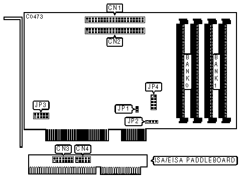
CONNECTIONS | |
Function | Location |
40-pin IDE (AT) Interface connector - IDE-0 | CN1 |
40-pin IDE (AT) Interface connector - IDE-1 | CN2 |
14-pin PCI legacy-header connector | CN3 |
10-pin cable connector to JP4 | CN4 |
2-pin connector - drive active LED | JP1 |
4-pin connector - cache error speaker | JP2 |
10-pin cable connector to CN4 | JP4 |
PCI INTERRUPT SELECTION | |||||
INT | JP3/jumper 1 | JP3/jumper 2 | JP3/jumper 3 | JP3/jumper 4 | |
| » | INTA | closed | open | open | open |
INTB | open | closed | open | open | |
INTC | open | open | closed | open | |
INTD | open | open | open | closed | |
USER CONFIGURABLE SETTINGS | |||
Function | Location | Setting | |
| » | Hard drive port address 1F0h and IRQ14 enabled | JP3/jumper 5 | closed |
Hard drive port address 170h and IRQ15 enabled | JP3/jumper 5 | open | |
DRIVE ACTIVE LED ERROR CODES (IMMEDIATELY AFTER POWER-UP) | |
Status | Function |
One short flash | No cache DRAM installed |
Two short flashes | CPU error |
Three short flashes | SRAM error |
Four short flashes | Timer error |
MISCELLANEOUS TECHNICAL NOTES |
Some versions of this board have two 512KB x 8 DRAM chips mounted in place of Bank 0. In such a case the board will work without additional memory. In all other cases a pair of 256KB, 1MB, or 4MB SIMM modules must be installed in Bank 0 for the board to function. The optional ISA/EISA paddleboard solves the DC-690B incompatibility problem with some early PCI mainboards. If installed, connect CN3 to JP4, and set JP4/jumpers 1-4 in the open position. |
My Books

